Get a demo
Platform
Platform Overview
Products
Reprise MCP
Enable agents to create personalized demos from customer context
Data Injection
Overlay and customize your live application in real time.
Product Tours
Capture your product, build a compelling demo, and share with your buyers.
Clones
Capture your product, build a compelling demo, and share with your buyers.
Capabilities
Security & Compliance
Analytics
Integrations
Shared Data
Solutions
Solutions Overview
Use Cases
Embeddable Demos
Live Demos
Sandbox Environments
Teams
Presales
Sales
Marketing
Resources
Blog
Guides
Webinars & Events
Newsroom
Demo Library
Why Reprise
Company
Careers
Customers
Pricing
Login
Get a Demo
Resources
Resource Center
|
featured Resource
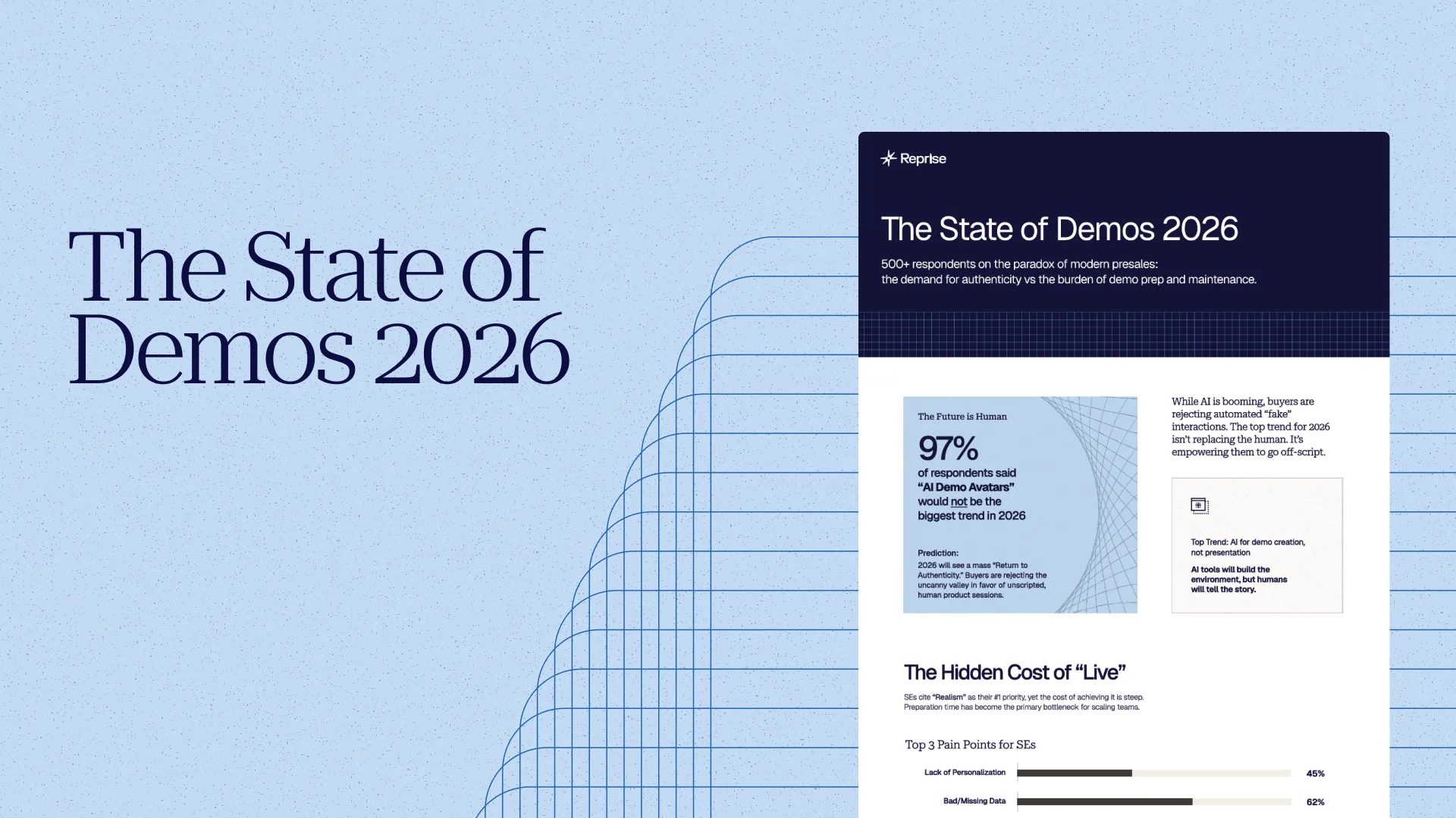
The 2026 State of Demos: AI Isn’t Coming for Your Job (But It Should Build Your Demos)
Continue Reading »
Blog
See All »
The Presales Leader's Guide to Measuring SE Impact
Continue Reading »
AI Can Sell Products, But Harder to Deliver Trust
Continue Reading »
Never Miss a Beat: Bringing "Presenter View" Confidence to Live Demos
Continue Reading »
Guides & Research
See All »
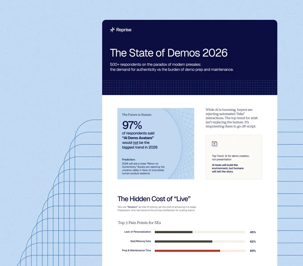
The State of Demos 2026 Report
Continue Reading »
The 2025 Sales Demo Report
Continue Reading »
Events & Webinars
See All »
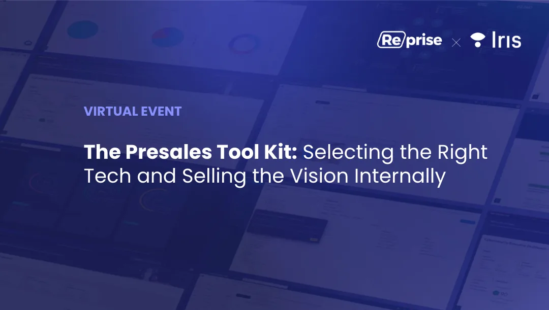
The Presales Tool Kit: Selecting the Right Tech and Selling the Vision Internally
Continue Reading »
Solution Heroes: Episode 9 - Hannah Bloking
Continue Reading »
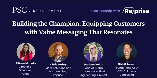
Building the Champion: Equipping Customers with Value Messaging That Resonates
Continue Reading »
Newsroom
See All »
Agent-shoring: The End of Offshoring?
Continue Reading »
Sam Clemens on Reprise, Demo Engineering & Scaling Product with AI
Continue Reading »
Reprise: AI & Human Trust
Continue Reading »